Viewpoint: On antenna placement for new wireless designs with 5G
Viewpoint: On antenna placement for new wireless designs with 5G

5G offers the advantage of greater data throughput and lower latency, and will enable a host of new mobile applications, for example in broadcast, robotics, Augmented Reality, Autonomous Driver Assisted Systems (ADAS), vehicle telematics, remote surgery and Cloud computing.
There is not much infrastructure yet for 5G in the UK, but it is eagerly awaited. The most popular frequencies for 5G are 2.3GHz, 2.6GHz and the 3.3-3.8GHz range. Europe has also prioritised 700MHz for 5G and the US has licensed 600MHz. In the UK mobile operators EE, O2, Vodafone and Three are all working at 3.4GHz with Three also using 3.6-4.0GHz.
These are much higher frequencies than those used for the existing 4G and LTE communications. These new band requirements will have PCB-level implications for new 5G designs that use surface mount device (SMD) antennas.
The earliest antennas supporting 5G were for 5G NR (New Radio standard), which arrived during 2018 to help the transition to real 5G. 5G NR supports the existing mobile bands, and the new wider ones supporting 5G.
Higher frequencies
While 4G wavelengths have a range of about 10 miles, the very high frequencies for 5G will have a shorter range, more like 1,000 feet. This means that 5G services will require much larger numbers of small cells to cover a local area.
The chief advantage of the higher frequencies will be the faster transmission of data. Download speeds of 150-250MBps should be feasible, compared to 20-30MBps for 4G and LTE. At these data-rates, it becomes possible to create time-critical applications that require an instantaneous response. The fastest 5G speeds of all will be in the mmWave bands above 24GHz.
Consequently, 5G will be best suited to ultra-reliable and low latency communications in urban areas where applications work over short distances, with line-of-sight. High frequency RF signals are relatively poor at passing through obstacles such as walls and glass, so outdoor applications will work best, and indoor applications are likely to operate through a repeater on a building.
Antenna size relates to frequency
Over the last few years there has been a strong trend towards the miniaturisation of chip antennas, and it is not unusual now for a Wi-Fi antenna to be as small as one millimetre across for single band applications. However, the high frequency bands used for 5G will require larger antennas.
The size of an antenna is directly related to the wavelength of the lowest frequency band it will operate on, and wavelengths are directly related to length of the antenna’s radiator and the ground plane it operates against. Higher frequencies use smaller wavelengths, and hence 5G antennas will need to be versatile to support the bands the device is intending to use.
Adding the 5G bands to an antenna means adding several bands: 600-617MHz bands, 3600-
4000MHz and up to 6GHz (5.9 GHz) which is required to meet US regulations. All of these ideally need to be supported in one antenna to build 5G devices that will operate anywhere in the world.
All this means that 5G brings a direct trade-off between size and performance. If a high performing antenna is required for 5G, it will need to be a little larger which will make the PCB designer’s job slightly more challenging. If a small antenna is chosen, it is likely to be less efficient and cover fewer bands of operation.
Ground plane allowance
SMD antennas usually require a surface on the PCB called the ground plane, which they bounce energy onto, to create a signal. The ground plane length is directly related to the wavelength of the antenna. It should be at least one quarter of the wavelength of the antenna’s lowest frequency, in order for the antenna to work efficiently.
The ground plane is usually a small space below or just adjacent to the antenna. Its size will be specified by the antenna manufacturer, and it varies from one antenna to another. This area should be kept clear of certain components, making it a key consideration in the PCB layout.
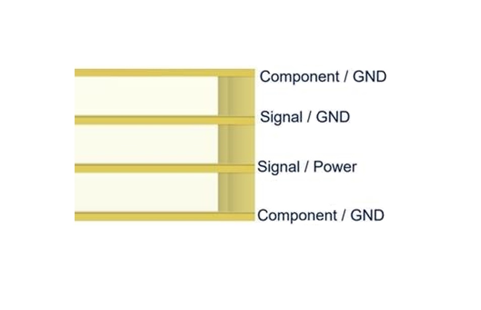
It is important that the copper ground plane is not too complex – it should not be cut up with traces or divided between layers. For multi-band frequencies we recommend a minimum four-layer PCB structure as shown in Diagram 1 below.
Where the ground plane is shorter than ideal, a designer can look at other techniques to increase the performance of an embedded antenna.
Tuning the antenna
An antenna can only operate at one frequency at a time, so one way to hone its performance is to tune it for its bands of operation. The device can effectively be tuned to operate in a narrower section of the frequency band, for the region where the device is to be used. This will boost the performance of the antenna.
MIMO / mmWave
MIMO is used to boost transmission rates at the very high mmWave bands. This requires a ‘true’ 5G device to have multiple antenna arrays on board. can significantly boost data transmission rates, however, this will use up more of the valuable space on the circuit board.
These two factors together mean that even more space is required to house antennas and to provide each one with sufficient ground plane space to operate efficiently.
Test phase
Every design should be tested in an anechoic chamber at a very early stage. This measures how well the antenna is going to perform on the PCB. Then two more tests will show how well the design will work in real life –Over-the-Air testing and specific absorption rate (SAR). SAR measures the level of energy absorbed by the human body, and is required to comply with safety legislation. The results of these tests will be measured as return loss, efficiency, and total radiated power.
These tests are crucial to ensure that the device will perform well, and that it will perform without creating interference on the cellular networks. In Europe, every new design for a wireless device has to be submitted for certification, to prove that it meets regulatory approval, before it can be used on the licenced cellular networks. In the US, the approvals are done by the cellular carriers. For now, the UK is remaining in line with European standards, and the certification requirements for 5G are not yet known.
Design choices
Designing a wireless device with an integrated antenna always needs care, and 5G is going to make it a little more challenging. Many 5G designs will need to be backwards compatible with the current 3G and 4G/LTE bands, so they will need antennas that cover a number of bands. Consequently, the antenna and its ground plane will need more space on the PCB to ensure performance. It is important to consider the antenna placement and layout first, before moving on to the rest of the design. Why? An antenna only works effectively in a few positions on a PCB, usually a side or a corner of the board. Unlike most components, its position is critical to its effective operation.
Citated:
Comments
Post a Comment